 |
Zerocat Chipflasher
v0.4.3 (board-edition-1)
Flash free firmware to BIOS chips, kick the Manageability Engine.
|
 |
Zerocat Chipflasher
v0.4.3 (board-edition-1)
Flash free firmware to BIOS chips, kick the Manageability Engine.
|
Thank you for purchasing — or having built — the Zerocat Chipflasher. We hope you will enjoy this cute tiny tool. Your feedback will be very much appreciated. Please contact zerocat@posteo.de for any questions or feedback and keep up to date with the Zerocat Chipflasher Git Repository.
The Zerocat Chipflasher is your free-design hardware tool for flashing free firmware to BIOS chips. Especially the chips, that are located on libreboot or coreboot compatible hardware are hopefully supported. See Supported Devices for details.

Parallax Propeller P8X32A free-design hardware controller
The core of the chipflasher...
Onboard eeprom (non-free chip design)
May be used optionally for long-term firmware storage.
Heavy Power Switch, Power Status LED and SPI Power LED
The switch gives a good tactile feedback when powering the flasher and the LEDs clearly reflect the power status of the onboard regulators.
RST Pin is muted and allows starting from RAM.SPI-Bus status LED (red)
When powered, the SPI-Bus is in use and the SPI chip is powered. Do not disconnect the SPI-Plug or test-clip if this LED is active!
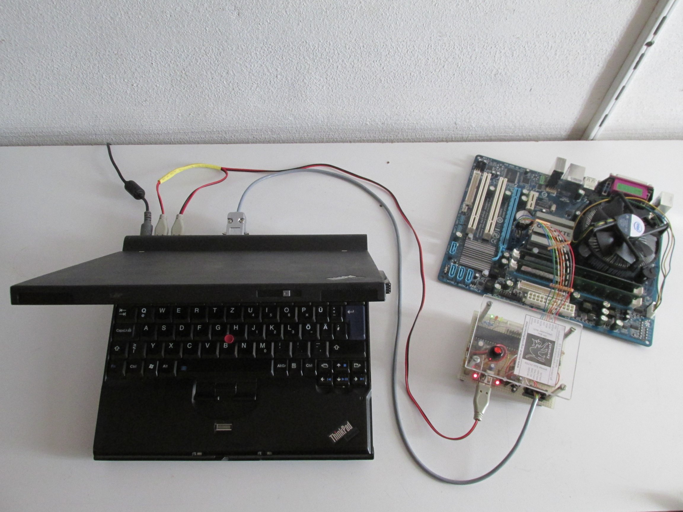
For now, the chipflasher board doesn't provide its USB port for data, it is used for power only. So, the typical setup is with a host that has an RS232 serial port available. We recommend to use a ThinkPad X60/X60s with pre-flashed libreboot or blobless coreboot BIOS. These machines can be flashed with the flashrom user space utility and the serial port is part of their docking station.
A typical setup looks like this:
You will use three cables for connection:
the USB cable for 5V power supply of the chipflasher board
(If you use two USB ports for power, use an Y-USB cable.)
+------------+                +-------------+           +·············+
| Host, i.e. |                | Zerocat     |           +---------+   :
|    X60 +   |                | Chipflasher |---+3.3V-->| SPI     |   :
|   Docking  |<--RS232-data-->|             |<---SPI--->|  Chip   |   :
|            |                | firmware:   |           +---------+   :
| software:  |      +--+5V--->|  'kick'     |           :             :
| 'connect'  |      |         +-------------+           : Systemboard :
+------------+      |                                   : without     :
                +--------------------+                  : Battery     :
                | External USB Power |                  : nor Power   :
                |  5V @ 1000mA       |                  +·············+
                +--------------------+
+------------+                +-------------+           +·············+
| Host, i.e. |                | Zerocat     |           +---------+   :
|    X60  +  |<--RS232 data-->| Chipflasher |---+3.3V-->| SPI     |   :
|   Docking  |                |             |<---SPI--->|  Chip   |   :
|            |----+-+5V-USB-->| firmware:   |           +---------+   :
| software:  |   /            |  'kick'     |           :             :
| 'connect'  |--+             +-------------+           : Systemboard :
|            |                                          : without     :
+----------- +                                          : Battery     :
                                                        : nor Power   :
                                                        +·············+

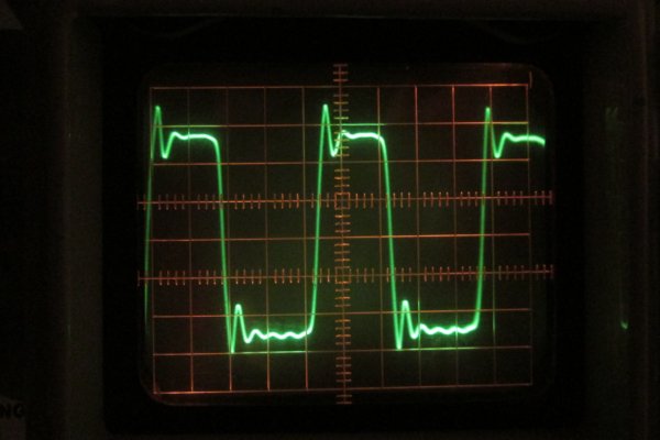
The Zerocat Chipflasher is a handmade tool with long wires that may generate or catch electromagnetic interference. To give you an idea about clock pulse quality and speed, we probed the signals right at the test-clip for you. The maximal SPI clock speed is about 2.5MHz.

You should have installed all essential tools according to README, section “Prerequisites”.
Connect host and chipflasher with each other, i.e. attach the Y-USB-power-cable to two USB-Ports, attach the RS232-data-cable.
Attach the SPI-cable, but omit the target board (or chip) for now!
Open a terminal and enter the chipflasher repository, i.e:
$ cd ~/zerocat/projects/chipflasher/
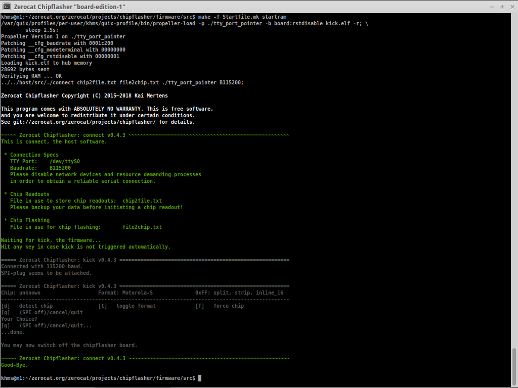
firmware/src/.make all.Type make -f Startfile.mk startram in order to initiate the firmware upload into the onboard EEPROM, and start immediatly.
sudo make ... instead.The Zerocat Chipflasher menu should appear on screen.
Success! Your setup is ready.
Hit “q” to quit and switch off the chipflasher board.

As default, the flasher uses the files chip2file.txt and file2chip.txt for data input/output.
In most cases, this flasher will be used to flash a newly created Coreboot or Libreboot ROM file which generally is available as binary data. Before you can flash it, you will need to convert your custom ROM into the file2chip.txt text file, preferable organized in lines of the Motorola S-Record format.
See Data Transfer and learn how to do that! Alternatively, see whether host/src/bin2srec.sh would be a suitable utility.
Sometimes, a coreboot ROM requires to extract binary blobs from the original vendor firmware. In that case host/src/srec2bin.sh will hopefully help you to convert your chip2file.txt into a binary image for further processing.
connect and the firmware kick are talking to each other via the serial RS232 lines. Occasional transmission errors will be repaired automatically. However, if you encounter severe connection problems that render you helpless when trying to verify your data, boot the host with WLAN and network switched off, make sure that no other resource demanding process will start up (e.g. browser), and try again.Attach the free pinheader connectors of the SPI-cable to the SPI-Chip...
Open a terminal and change into firmware/src/.
Now switch the chipflasher board on.
Type make -f Startfile.mk loadram in order to upload the firmware into the flasher’s onboard free-design RAM.
Then type...
make -f Startfile.mk start orhost/src/ and type: ./connect chip2file.txt file2chip.txt /dev/ttyS0 B115200The menu should arise on screen.
Choose “[d] detect chip” in order to probe the BIOS-chip.
If not succesful, use a screwdriver in CCW direction to adjust the CE# pull-up resistor to smaller values and try again.
If successful, you may now use the menu for dumping, erasing, flashing and verifying your chip.
Try “[r] show status register” to see the chip’s current configuration.
[c] read chip”. The data will be stored in chip2file.txt, for example.file2chip.txt, typical steps are:[c] read chip”.diff the files, i.e.: diff backup.txt chip2file.txt.[W] set status register”, [X] global sector unprotect” if provided.[C] erase chip”.[I] flash file”.diff command after having converted file2chip.txt and chip2file.txt into the same layout with srec_cat. See Data Transfer for details and examples or see whether host/src/diff-srec.sh would be a helpful utility to accomplish this task.Wait until your choosen procedure finishes. With “[q] (SPI off)/cancel/quit” you may cancel it at any time.
Hit “q” in order to quit connect.
q”.Power off the chipflasher board and detach the SPI-cables from the target SPI-chip.
Done!
Until now, we have taken care to always start from RAM using commands like
make -f Startfile.mk loadram, followed by make -f Startfile.mk start,make -f Startfile.mk startram.The pre-flashed firmware in the onboard EEPROM has not been touched, yet.
If you want to try the pre-flashed firmware, just issue a single
make -f Startfile.mk start.If you want to upload a newly built firmware and make things permanent, just use
make -f Startfile.mk startrom ormake -f Startfile.mk loadrom once.From then on, you may start your flasher with a single command:
make -f Startfile.mk start or, alternatively,host/src/ and type ./connect chip2file.txt file2chip.txt /dev/ttyS0 B115200.The latter command would allow you to pass individual parameters to ./connect.
Script utilities like bin2srec.sh, srec2bin.sh and diff-srec.sh would be available in the same folder, host/src/.
 1.8.17
Zerocat’s note on JavaScript licenses: All JavaScript files of this page are free software. Generated files (dynsections.js, menu.js, menudata.js) carry doxygen’s GNU GPLv2 license header. File jquery.js is minified code but points to corresponding source files, which in turn provide their own license infos. In case the GNU LibreJS Browser Extension complains about these scripts being non-free – please whitelist them manually and reload the page.